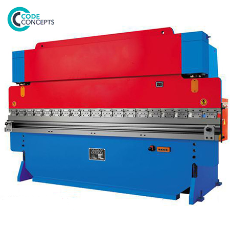
Hydraulic Press Brake
Technical Specifications
Model WC67Y
100T/2500
100T/3200
160T/3200
160T/4000
Nominal Pressure
1000 kN
1000 kN
1600 kN
1600 kN
Worktable Length
2500 mm
3200mm
3200mm
4000mm
Distance between
panels
1900 N/mm²
2600 N/mm²
2600 N/mm²
3400 N/mm²
Throat Depth
300 mm
300 mm
340 mm
340 mm
Slide Stroke
140 mm
140 mm
200 mm
180 mm
Max Opening Height
390 mm
390 mm
440 mm
440 mm
Slider Stroke Speed
70 No load
8 work
60 return
70 No load
8 work
60 return
70 No load
8 work
60 return
70 No load
8 work
60 return
Main Motor Power
7.5 KW
7.5 KW
11 KW
11 KW
Overall Dimension
2.9×1.7×2.5 m
3.3×1.7×2.5 m
3.7×1.9×2.7 m
4.5×1.9×2.8 m
Model WC67Y 200T/3200,300T/4000
Model WC67Y
200T/3200
300T/4000
Nominal Pressure
2000 kN
3000 kN
Worktable Length
3200mm
4000mm
Distance between
panels
2500 N/mm²
3300 N/mm²
Throat Depth
360 mm
400 mm
Slide Stroke
200 mm
250 mm
Max Opening Height
480 mm
540 mm
Slider Stroke Speed
60 No load
8 work
50 return
60 No load
6 work
50 return
Main Motor Power
22 KW
22 KW
Overall Dimension
3.7×2.2×2.9 m
4.5×2.5×3.65 m
Main Structure
1. Frame part:
WC67Y Series hydraulic press brake machine adopts hydraulic driven, frame part includes ram, cylinder and mechanical chock block micro-metric setting. The length of ram travel can be regulated arbitrarily, if the bent workpiece unnecessary with too long travel, will adjust travel by mechanical chock block, thus higher work efficiency obvious. The left and right cylinders are fixed upon the frame, let piston to driven ram lift up and down by the hydraulic system.
2. Worktable part:
Installed four compensation cylinder in vertical sheet plate of the worktable, can to reach better press brake performance. To control worktable by the button in the front of the worktable, let motor-driven stock frame-level move, and logical display the movement, installed position switches at the front and back limit stations.
3. Slider part:
Slider part is composed of the slider, cylinder and mechanical block fine-tuning device. It adopts overall panel structure, left and the right cylinder is fixed on the machine frame, through a hydraulic piston (rod) driven slider doing up and down movement.
4. Synchronous system:
The synchronous construction of this device composed of twist shaft, swing beam, this structure is simple, performance is reliable and steady, synchronous accuracy is high.
5. Back gauge Device:
Manipulated by the button box before the working table, make the motor-driven gauge frame moving, and has moving distance digital display, the minimum reading of 0.10 mm. Front and back position both have stroke limit switch.
6. Accuracy compensation mechanism:
The fine-tuning mechanism is installed on the upper mould, used for up and down compensation fine-tuning, in order to guarantee the bending accuracy. Sometimes, when bending, the angle degree in the total length has a slight deviation, in order to get the consistency of the bending angle degree, you can loose the screw, move the Oblique block, then doing fine-tuning on the upper mould, then tighten the screw, re-bending till meet your requirement.
7. Electric System:
Main Power supply: 380V, 50Hz, three-phase,
Control power supply: 220V 24V.
The main circuit and the motors are using automatic switching circuit and overload protection. The control loop sections are using the short-circuit protection fuse. The main mechanical components are grounded.
The machine has three ways of working, by the universal switch SA3 to select jog, single, continuous.
Machine operation is controlled by a footswitch, convenient and fast.
Electric components are the Siemens brand.
The line is simple, safe and easy to maintenance.
8. Hydraulic System:
The hydraulic system consists of a motor, axial piston pump, valve, fuel tank, fuel lines and hydraulic accessories.
The maximum working pressure of the hydraulic system is 25MPa, set through the main loop system valve.
Contact Us
Tel: +91-9600881584
Email: [email protected]